Quantcast
Channel: Analog/Custom Design
Viewing all 750 articles
Browse latest View live

Virtuosity: 14 Things I Learned in May 2015 by Browsing Cadence Online Support

$
0
0

Cadence Documentation

1. Cadence Documentation Survey

Cadence is committed to providing high-quality documentation. To help us shape the future of Cadence documentation delivery, we welcome you to complete our survey.

Application Notes

2. Virtuoso Spectre Transient Noise Analysis

This document discusses the theoretical background of the Spectre solution’s transient noise analysis, its implementation and implications, and the latest use model together with many useful simulation time-saving and circuit diagnostic features. Most importantly, this application note provides a very detailed tutorial example with the Virtuoso ADE environment, a few periodic steady-state circuits to show the correlation with periodic steady-state noise analysis (pnoise), and the use of transient noise analysis on its main application - nonlinear and non-periodic data converter designs.

3. Calibrated Verification with ADE XL

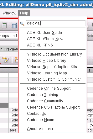
This application note focuses on one of the most important types of advanced analog and mixed-signal verification, which is verification in the calibrated condition. It provides explanations and examples of using ADE XL features such as the calcVal() function, Verilog-A blocks, and pre-run scripts.

4. Virtuoso Analog Design Environment XL: Variables, Sweeps and Corners

A "best practices" document covering topics on the use of variables, sweeps, device parameterization, corners setup, results filtering, datasheets, and spec comparison in ADE XL.

Rapid Adoption Kits

5. Jee Measurement Using PSS/Pnoise and Transient Noise Analysis

Jitter is a key measurement in systems where the periodic behavior or exact event timing is crucial to system performance. Various jitter metrics characterize the statistics of the observed sequence of events. This variation in the delay between a triggering event and a response event is the edge-to-edge timing jitter. It is also called as absolute or aperture jitter. This RAK demonstrates how to do Jee measurement using Pnoise and Tran noise.

Videos

6. Virtuoso Analog Auto Placer

This video discusses the basics of analog placer, capture design constraints in schematic, capture modgen constraints, and automatic placement using the analog placer.

7. Save and Plot Operating Point Parameter for Transient and DC Sweep and Save Subckt Instances in ADE L & ADE XL

In this video, you will see how to save and plot operating point parameters for transient and DC sweep analysis for Spectre simulator from ADE-L and ADE XL. It will also cover how to specify hierarchy levels to save subckt Instances in ADE L and ADE XL.

8. Supporting the Pspice View

This video shows how to create a Pspice view and then perform Spectre-based netlisting by using this view.

Training Bytes

  • Virtuoso Connectivity-Driven Layout Transition IC6.1.6
  • Skill IDE

Blogs

9. EDPS 2015: Choosing FinFET, FD-SOI, or Bulk Planar FETs

If you’re designing an IC today, you have three types of transistors to choose from – traditional bulk planar FETs (down to 20nm), FinFETs (below 20nm), and FD-SOI (fully depleted silicon-on-insulator, 28nm). How can you make the best choice for your design? A session at the recent Electronic Design Process Symposium (EDPS 2015) provided a wealth of information to help you decide.

Solutions

10. How to Run a dc Without Saving dcOpInfo

You are running a dc simulation. You have save=selected in ADE. You are running on an extracted view.  The dcOpInfo analysis that comes along with dc is very large and filling up your disk. Can you run dc without it?

11. New Spectre +dcopt Option to Help dc Convergence

You are running a large Spectre simulation and you are having trouble converging in dc. You have done all the suggestions printed in the spectre.out file after convergence failure. What else can you do?

12. VLS- XL: Cross Highlighting Net Between Layout and Schematic Window

In XL mode, when I select a net in the Virtuoso Schematic window, corresponding net gets selected on the layout side. However, it does not work vice versa.  I am selecting a net (path segment) on the layout side; however, the corresponding net in the schematic is not getting selected. How can I get it to work?

13. Example of How to Use axlReadHistoryResDB to Access Scalar Result Database in ADE XL

You have run some simulations in ADE XL (either from the UI or using OCEAN XL), and want to know how to traverse the result database (the "RDB") to access the scalar results and information about the simulations performed. You have read the documentation on axlReadHistoryResDB and understand that this returns an object which you can traverse points, corners, outputs and so on - and it has built-in help. However, you would like an example which iterates through all the results, giving information on the sweeps, the corners, the tests, and the outputs, structured in the correct order.

14. How to Restrict Spectre APS to Use the Number of Threads Reserved by LSF?

You are submitting Spectre APS simulation jobs on LSF. While submitting the job you are using +mt or +mt=8 and do not reserve the required cores using "-n " in the LSF command string. Due to this the LSF allocates a single core for the job, but Spectre APS ends up taking more than 1 core without any message. This results in affecting the other jobs that are running on the same machine.  How can I restrict Spectre APS to use threads reserved by LSF?

Stacy Whiteman


Things You Didn't Know About Virtuoso: Help Us to Help You

$
0
0

There is a team at Cadence working on developing the next generation of Cadence documentation and Help interface.  After rolling your eyes at this statement, I'd really like you to take 10 minutes to complete our brief (honest) survey to help us improve our documentation delivery in the future. 

Here's the link: Cadence Documentation Survey

And in case you haven't looked under the Help menu in your Virtuoso window lately (and I know you haven't), that interface has been significantly enhanced to include direct links to the documentation for the product you are using, the Cadence Online Support website, Virtuoso Community pages, and many other helpful sources of information. There's even a search field at the top of the Help menu so you can search the documentation library directly from the application window.

Thanks for filling out the survey!


Stacy Whiteman

Virtuosity: Things I Learned in August and September 2015 by Browsing Cadence Online Support

$
0
0

Cadence Online Support Features

Setting the Release Preferences for your search results: The documents in the search results page often support multiple releases. You now have the option to set preferred release(s) for your default search on the home page search. Check out My Support – My Accounts and Preferences, Release Preferences. For example, you may set “IC 6.1.6” as the preferred release and ensure that the search results page displays IC 6.1.6 documents as the default out of multiple values.

Also, use My Support->What's New to learn about additional new features in COS.

Application Notes

Setting up Liberate MX for Various Usage Models: This application note is intended to assist you to understand the purpose and method of Liberate MX and to guide you to choose the usage model that best suits the design that they are characterizing.

Rapid Adoption Kits

PVS Configurator: PVS Configurator in PVS 15.1. Using configuration files and letting the designers make choices and save them for subsequent runs is an effective way to provide the options to the designer. Using a configuration file also lets the designers choose options directly from the main rule file supplied by the foundry.

Precompiled libraries and Automatic Package handling by UNL for AMS Simulations from Virtuoso ADE: HDL languages require file/library-specific options/bindings that must stay consistent throughout the design development cycle. The use of Verilog/VHDL packages need careful attention and are better managed as precompiled objects and are shared between all source codes requiring them. Design cycles can be better optimized by reusing precompiled objects and sharing them with multiple design groups.

Crystal Oscillator Simulation using SpectreRF: Crystal Oscillator is one of the class of oscillators that brings its own challenges to simulate. One of the key challenges it brings to simulate is a long startup time. The purpose of this document is to make suggestions regarding best practices for simulating crystal oscillators. A database composed of the circuits needed to reproduce these results is provided separately. This RAK demonstrates a method to do Crystal Oscillator simulation using SpectreRF Analyses. Initially a transient analysis is done and then Hb/Hbnoise analysis is used to determine the oscillation frequency and the phase noise of the oscillator.

PVS-Based Constraint Checking in Constraint Manager: This RAK steps through the PVS-Based Constraint checking in Constraint Manager.  What you will learn: An example to validate routing constraint.

Virtuoso Floorplanner - API/SKILL Based Flow: The Floorplanner flow increases layout productivity through improved floorplanner functionality aimed at block-level interconnect. Instead of using GUI commands, we can use SKILL APIs to generate a physical hierarchy (layout from schematic in a hierarchical manner) in Virtuoso Floorplanner flow.

Videos

Training Bytes (new or updated videos from the following Training Courses):

  • High-Performance Simulation Using Spectre Simulators vMMSIM14.1 with IC616
  • Real Modeling with SystemVerilog vINCISIVE14.2
  • Virtuoso Layout Pro
  • Virtuoso Space-Based Router
  • Physical Verification System v15.1

Making a layout XL-compliant using Update Binding (XLME): Often layout engineers have existing or legacy layouts that they wish to use in VLS XL to take advantage of the connectivity-driven flow. With turnaround time increasingly important, the ability to reuse an existing layout in an advanced, connectivity-driven environment is necessary. With the introduction of the Update Binding functionality in IC6.1.6, it is now possible to quickly make a legacy layout fully XL-compliant. This is required to access the advanced functionality of layout XL and GXL. What you will learn: What is XL-compliance; Checking XL-compliance; Update Binding; Update Binding using the output of a PVS LVS run.

Creating Stripes Using Power Router: This video demonstrates power routing GUI and the SKILL rtePowerRouteStripes command.

Solutions

How to define compiler directive macro to run digital corner sweep in ADE XL? You have  compiler directive macros defined in your digital code.  You want to define these macros as a sweep in ADE XL to run digital corners in ADE XL, how to do this?

How to find the signal name saved using wildcard operator with save statement in spectre? You are using wildcards in Spectre for saving signals selectively and thus reducing runtime, memory usage and disk space.  If you use wildcard as following, "save *", it will save all node voltages and in spectre.out file you will get following message concerning wildcard match summary: Wildcard match summary: save * nodes: 68.  You want to get the name of all the nodes saved using wildcard operator. How to get this information?

How to prompt user to select Job Policy based on particular run mode in ADE XL? You have set a default Job Policy for ADE XL say "Def_Job_Policy". Unless user change, this Job Policy will be used for all run modes in ADE XL. But for "Monte Carlo" simulations you have defined a Job Policy say "MC_Policy" which is preferred for running Monte Carlo simulations. Switching in different run modes user may forget to change the Job Policy while running Monte Carlo simulation.  You would like to prompt user with option to selected "MC_Policy" when running Monte Carlo simulation.

Elapsed time slower in OCEAN than in ADE: You are running a simulation in an OCEAN script which you are loading from the CIW. You are finding that the elapsed time of the simulation is significantly slower than when run from within ADE. You've checked the netlist (e.g., input.scs) between the two runs and they are identical.  What could be the reason for this, and is there a workaround?

Virtuoso Schematic Editor, Edit Properties form does not display evaluated value of pPar and iPar expressions. How to know evaluated value of such expressions? I have a CDF parameter named Area for one of the nmos4 symbol. Its value is iPar(l) * iPar(w), i.e., length X Width of the instance. I want to know the evaluated value of the given instance Area parameter. Since Edit Properties can't show it I am looking for alternate means to know the value. Possibly a label or annotation.  Is there a way to display evaluated values of iPar and pPar expressions present on an instance CDF parameter?

 FAQ:  Spectre RF Convergence Tips for Shooting PSS Analysis: The article is divided into four sections:

  • Section 1: General aspects of steady-state computations
  • Section 2: Common problems
  • Section 3: Special considerations for oscillators
  • Section 4: Advanced debugging and convergence assist techniques

 How to turn on "Save data to allow family plot" by default in Monte Carlo options form in ADE XL? You are running Monte Carlo simulations from ADE XL. You would like to set "Save Data to Allow Family Plot" ON by default.

New ie card gui makes customizing connect rules easier You are using AMS Designer in ADE.  You want to customize the connect rules. Using Built in rules, this is very cumbersome. You need to edit the same information for every connect module.

SKILL script to run simulation at preset timing Due to lack of simulation licenses, it is sometimes desired to run simulations at preset timings (e.g., after midnight, etc) when more simulation licenses are available. This article contains a SKILL script which allows a user to run a simulation for various simulators (e.g. ams, spectre, etc) at a future date and time. The script uses linux "at" cmd to schedule a time for executing "runSimulation" file in the simulation directory.

Virtuosity: Things I Learned in June and July 2015 by Browsing Cadence Online Support

$
0
0

Cadence Online Support

Release Highlights July 2015
Some nice enhancements to the COS experience. Ability to set preferred release for searching, better interface for navigating search results in product manuals.

Using Case Groups: User Roles and Sub-Group
This video shows the functionality provided by Cadence Online Support to share viewing and administering of Cases

Application Notes

Virtuoso Analog Design Environment XL Signals, Expressions, and the Calculator
A "best practices" document covering topics including creating expressions, using the ViVA Calculator, measurements across corners, re-evaluating expressions, and using OCEAN measurement scripts.

What's New in CAT/HED - IC616 ISR12 / ICADV121 ISR14
This document describes what's new in Virtuoso infrastructure in IC 6.1.6 ISR12 (IC6.1.6.500.12).

PVS Multi/Distributed Processing
This document provides introduction and examples of job submission process for multi-processing jobs in PVS.

Pc.db Auto Support for Read-Only Libraries
Documents a new automatic mechanism to update pc.db files for read-only libraries. 

Spectre and APS Non-Convergence Debug Guide
Needs no explanation. Just go get it.

Understanding Statistics in PVS DRC Report
The purpose of this document is to explain the meaning of statistics shown in PVS DRC Error report using a simple example. It also touches upon the default display format of the errors in DRC Debug Environment and how to change that default.

Update Training

IC 6.1.6 What's New Library
This is a new initiative across several groups within Cadence to provided a detailed document and videos to overview core new and enhanced features in ISR releases. It covers IC 6.1.6 ISR7 – ISR12. From the COS front page, select Self-Help->Update Training. Bookmark this page to learn about the latest IC Virtuoso release offerings.

Rapid Adoption Kits

PSPICE netlist support in ADE
Spectre supports PSPICE netlist format targeting to include PCB components that are modeled in PSPICE format. This solution does not support PSPICE only designs. A top-level netlist and control statement need to be defined in Spectre, or SPICE format. The recommended approach is to define a subckt in PSPICE netlist format and to instantiate that subckt in a Spectre netlist.

IC6.1 Front to Back Overview (updated for IC6.1.6 ISR12)
What you will learn: Design creation and constraint capture in the Virtuoso Schematic Editor; design analysis and verification with the Analog Design Environment; constraints; Virtuoso environment; buses; constraint aware editing; fluid guardring; Virtuoso spaced-based router; and interactive routing.

Schematic Model Generator (updated for IC6.1.6 ISR12)
Virtuoso Schematic Model Generator (SMG) is tightly integrated into the Virtuoso design environment and enables the generation of analog/mixed-signal behavioral models using a schematic-like representation of the behavioral model. The schematic view is then processed to generate the behavioral model. With this approach, behavioral modeling becomes easier to comprehend, communicate to involved team members, and is better managed compared to manual textual entry.

Videos

Training Bytes
New videos from Cadence training courses on the following topics:

  • Virtuoso Connectivity-Driven Layout Transistion
  • Using Virtuoso Constraints Effectively
  • Virtuoso Space-Based Router
  • Physical Verification System

PVS Interactive Short Locator
Two videos—"Finding Shorts" and "Confirming the Cause of Shorts Without Modifying the Layout" 

Solutions

Fluid Guard Ring Frequently Asked Questions


How to suspend and resume simulation runs in ADE XL?
You are running simulation using ADE XL environment. While running resource-intensive simulations, if sufficient disk space is not available, you would like to suspend simulations, clean up disk space, and resume them for completion. How can you do this?

Performance Utility to debug Virtuoso Layout Editor performance
How to use the Performance Utility in Virtuoso to debug Virtuoso performance

How to auto update state in ADE L/XL without getting a prompt?
How can I disable the dialog boxes and have the state auto upgrade in background?

How to generate ADE XL datasheet in different format (pdf, svg, etc)?
Describes an environment variable that will allow the waveform snapshots (not the entire datasheet) to be saved in an alternate format for better image resolution.

How to control the number warnings/notes printed on screen and in log file during spectre simulation?
Flexible controls for limiting and filtering warnings and notices from Spectre.

How to change the position of the Direct Plot form on my screen?
You are using ADE L/ADE XL. The Direct Plot form pops-up in the middle of your screen, which is not convenient for you. Is there a way to change the location where Direct Plot form appears?

How to add termMapping for a subcircuit included from ADE model file option during ADE Spectre simulation?
You would like to use external spice or spectre netlist in your ADE spectre simulations. You would be including this external sub-circuit netlist from ADE Model files GUI. Your test bench contains just the ‘symbol’ and ‘spectre’ view of this sub-circuit created by you manually. You have added some ‘save’ statements in ADE outputs by selecting the terminals of the symbol from schematic. When you simulate with ADE spectre, simulation runs fine but your ‘save’ statements are getting ignored and you cannot auto plot any of the terminals of that external spice netlist.

How to disable port order checking for text view vs symbol view?
Your text view port order is different than the symbol view port order for the same cell. You want to disable the port order checking, but still want to check for mismatched pins. And you want to turn off the resulting dialog box that pops up.

New transient analysis memory estimator available
You are simulating large, memory-intensive circuits and would like a "memory estimator" for transient analysis similar to the one already available in hb analysis.

Virtuoso Schematic Editor: Instance objects labels un-selectable
In Virtuoso Schematic Editor window, how can I select Instance-related labels? 

How to apply same process variations between two related tests in Virtuoso ADE XL Spectre Monte Carlo analysis?
You are running Monte Carlo simulations with Spectre in Virtuoso ADE XL. You have two or more tests created in your ADE XL setup and would like to apply same process variations to both these tests as these related tests or dependent tests. Starting MMSIM13.1 ISR8, a new Monte Carlo analysis option has been added to Spectre which ensure that same process variations are applied to different netlist/tests.

How to get the path to the netlist directory of each test in Virtuoso ADE XL using SKILL?
How to get the path to the netlist directory of each test from latest run (last history item) in Virtuoso ADE XL using SKILL?

How to set CDF termOrder to be used always, if present, during Netlisting?
You are creating a Spectre netlist from Virtuoso ADE. In the netlist which gets created you see that the CDF termorder is not followed. How can you set CDF termOrder to be followed always, if present?

How can I save selected variables from Verilog-A models? 
You have several Verilog-A models in your design, and in order to debug a problem, you'd like to be able to save selected Verilog-A internal variables and plot them after simulation. You are aware that on the Outputs->Save All form you can set saveahdlvars to all but this will require you to save all internal variables from all Verilog-A modules in the design.

Job policy change per ADE XL session
You have multiple ADE XL sessions running. They are all using the same job policy. You notice modifying job policy in one of the ADE XL sessions will change job policy for all ADE XL sessions. You want your changes to the job policy to just affect your current session. How can you do that?

How to correctly set up the command to use in a Virtuoso ADE XL job policy
You wish to use command mode for your job policy—this is where you specify the command used to submit the job using your Distributed Resource Management system rather than using the built-in LBS interface to LSF (from IBM's Platform Computing) or SGE (Sun Grid Engine, or more recently Univa Grid Engine). Is there anything in particular you should take care of when deciding how the job should be submitted?

How to restrict Virtuoso ADE XL ICRP process to run specified number of points?
You have setup Job Policy to run multiple ICRP processes. You would like to run particular number of points with one ICRP. The ICRP process should be killed after running specified number of points and if required start new ICRP process till all points are completed.

Library Manager minimizes rather than exits when the Window Manager X button is pressed
You are using IC616 ISR12 or later (or ICADV12.1 ISR14 or later) and have noticed that when you use the "X" button in the window of the library manager to close it, the library manager minimizes rather than closes. This did not happen in earlier versions. Why is this?

SKILL Information

Refreshed Custom IC Design SKILL Code Library
Custom IC Design SKILL Code Library has been refreshed! This library provides you a set of the most popular SKILL codes to instantly boost your SKILL code examples and enhance your design productivity.

Virtuoso Video Diary: Introducing WSP Manager

$
0
0

Are you an advanced node layout or CAD engineer trying to find a methodology for routing designs in the Virtuoso platform? Interested to learn how to specify tracks for correct-by-construction designs using width spacing patterns (WSPs)? If you are not using the WSP Manager in the Virtuoso environment to create and modify your WSPs, now is the time to try it.

Using Width Spacing Patterns for Advanced Node Designs

Advanced node design demands extensive additional design rules. Width spacing patterns are used to maintain those rules and define tracks with specific widths and spacing for interactive placement and routing. Previously, you defined WSPs in the foundry’s technology file or using SKILL.

WSP Manager was introduced in ICADV12.2 ISR5 as a convenient GUI for creating and modifying WSPs. You can also preview WSPs to visualize exactly how they would appear in your layout, before saving them to your design database. You can share WSPs amongst your team by importing WSPs from a common cellview. If your design has placed instances and objects, you can easily generate a WSP grid from those shapes. To find out how to use WSP Manager, watch these videos on Cadence Online Support:

Note: Cadence Help supports native playback of videos (mp4) added to the installed Virtuoso Documentation Library. Look under Video Demos for a video topic of your interest.

Related Resources

What's Next

Virtuoso Video Diary will next bring to you a set of videos on the SKILL IDE performance analysis tools that include Code Browser, Lint Manager, and Profiler. These tools help you assess the performance of your SKILL code and identify any areas of improvement. The related videos demonstrate the key features of these tools that can help you refine your SKILL code. Stay tuned…            

About Virtuoso Video Diary

Virtuoso Video Diary is envisaged to be an online journal that will relay information about Virtuoso videos that are available in the Cadence Online Support Video Library. For IC6.1.7 and ICADV12.2, over a hundred videos on a wide variety of new and exciting Virtuoso features have already been created. Virtuoso Video Diaries brings you direct links to these videos and other related material, on regular basis, in your mailbox. Subscribe to receive the e-mail notifications.

Virtuoso Video Diary: SKILL IDE Performance Analysis Tools

$
0
0

As a SKILL code developer, do you spend a major chunk of your time in fine-tuning your SKILL code? I am sure nobody writes perfect code in the first attempt. Producing efficient and bug-free code involves several iterations of proactively monitoring the code, eliminating bottlenecks, and analyzing as well as improving its performance. And there are tools that can help you improve your code’s performance without affecting its behavior.

Hey, don’t panic! I am not asking you to learn any new tools. Everything you need for improving the performance of your SKILL code is available within Cadence SKILL IDE. We don’t call it an ‘Integrated Development Environment’ for no reason!

SKILL IDE offers the following three tools to help you find what ails your code:

  • SKILL Code Browser

Code Browser is a source code navigation and analysis tool, which allows you to browse your code without having to keep track of the declarations and references of each program element. It is designed to enhance your ability to understand and modify your SKILL programs. Using the Code Browser, you can view the call graph of user-defined functions. You can also jump directly to the definition of the function selected in the Code Browser window. In short, Code Browser helps you keep an eye on your code without overly complicating things.

  • SKILL Lint

SKILL Lint can be used for statically checking SKILL and SKILL++ programs for possible errors and inefficiencies that may go undetected during normal testing. SKILL Lint also provides hints about improving the efficiency of your code. So, like a good friend, SKILL Lint points out the issues in your code and gives you hints on fixing them.

  • SKILL Profiler

SKILL Profiler is a performance analysis tool that provides information about the run-time behavior of your code. Using the Profiler, you can identify the functions that are consuming the most time or memory during a run. You can then evaluate these functions for possible performance improvements. In short, SKILL Profiler keeps the guesswork out of performance analysis.

Watch the following videos on Cadence Online Support:

NoteCadence Help supports native playback of videos (mp4) added to the installed Virtuoso Documentation Library. Look under Video Demos for a video topic of your interest. 


Related Resources

  • Cadence SKILL IDE User Guide 

What's Next

Virtuoso Video Diary will next bring to you a set of videos on Symbolic Placement of Devices (SPD), a row-based symbolic placer that lets layout engineers perform quick and easy placement of PMOS and NMOS devices. These videos will help you get started with using SPD and understand some of its prominent features, such as smart move, multirow placement, signal trunks, and user-defined abutments. Stay tuned…

About Virtuoso Video Diary

Virtuoso Video Diary is envisaged to be an online journal that will relay information about Virtuoso videos that are available in the Cadence Online Support Video Library. For IC6.1.7 and ICADV12.2, over a hundred videos on a wide variety of new and exciting Virtuoso features have already been created. Virtuoso Video Diaries brings you direct links to these videos and other related material, on regular basis, in your mailbox. Subscribe to receive the e-mail notifications. 

Virtuoso Video Diary: SPD – A Symbolic Way to Edit Your Physical Design

$
0
0


The best way to complete a complex task is to break it into smaller, simpler tasks.

This is exactly what Symbolic Placement of Devices, popularly known as SPD, does for layout engineers. SPD is a symbolic row-based placer. Designed primarily for small to medium-sized designs, SPD displays only the relevant information needed to perform device placement. Using SPD layout, engineers can easily edit device placement, preview the updated designs, and finally, generate the layout.

Why Do I Need a Tool Like SPD?

The design rules for real devices are constantly increasing. As a result, the amount of computation needed to perform any task, starting from Pcell evaluation right through to device placement, has also increased by many times.

Several applications perform complicated post-processing tasks to get a DRC error-free design. SPD helps you avoid most of these additional tasks and heavy computation during editing. Complexity comes into picture only when you preview the design. This is when the tool converts symbolic devices to real devices.

Row-based Placement

The prime focus of SPD is to improve productivity of layout designers by facilitating quick and easy placement of PMOS and NMOS devices. By default, the symbolic layout arranges devices in an NP row pattern. The top row (P row) of the design, represented in red, contains the PMOS devices and the bottom row (N row), represented in green, contains the NMOS devices. SPD supports several row patterns that you can use to optimize your design.

Row-based Placement in Symbolic Placement of Devices


The Benefits

Among the several benefits of SPD, the top three are:

  • Symbolic - Symbolically represented devices, with neatly drawn orthogonal flight lines, minus any complex data, are easy to understand. Editing placement of these devices is a lot simpler than real devices.
  • Simplicity - The simple use model of the SPD commands enables device placement in just a few mouse clicks
  • Speed - Editing in SPD is much faster than editing real devices on the main layout canvas

Getting Started with SPD

To get you started with SPD and help you learn more about the tool, we have created a few videos to demonstrate its various features:

Click the video link now OR visit Cadence Online Support and search under Resources — Video Library for the video title.

Note: Cadence Help supports native playback of videos (mp4) added to the installed Virtuoso Documentation Library. Look under Video Demos for a video topic of your interest.

Getting Started with Symbolic Placement of Devices

This video demonstrates the complete SPD flow. It also shows how to use some of the main commands, such as smart move, abut, and generating chained devices.

 SPD Flow

Performing Multi-row Placement in SPD

SPD supports several row patterns, such as NP, PN, NPPN, PNNP, NPNP, PNPN, NNPP, PPNN, NNNP, PNNN, NPPP, PPPN, NNNN, and PPPP. The video shows how using multiple row patterns in SPD helps in optimizing a design.

 Multirow Placement in Symbolic Placement of Devices

Creating Signal Trunks in SPD for Pin-to-Trunk Routing

Flight lines in the symbolic design can be converted to signal trunks. These trunks can be directly used for pin-to-trunk routing in layout. The combined flow can provide up to 10X productivity gain. Check out the video to see how to create signal trunks in SPD and then use them for pin-to-trunk routing in Virtuoso Layout Suite XL.

 Creating Signal Trunks in SPD

Using User-Defined Abutment and Callback Functions

In advanced node designs, to perform PDK-specific abutments, such as dummy poly abutment, you might need to define your own custom abutment callback functions. You can enable user-defined abutment in SPD by loading the callback functions and registering them before launching SPD. Otherwise, only the default oxide diffusion abutment will take place.

SPD also supports the user flow callback functions that further help in customizing the design in specific steps of the SPD flow. Although particularly useful at advanced nodes, the user flow callback functions are also supported in mature node versions.

The video demonstrates the SPD flow when you have defined the user-defined abutment and user flow callback functions.

Related Resources

NoteFor more information on Cadence products and services, visit www.cadence.com.

What's Next

Virtuoso Video Diary will next bring to you a video on the Net Class Group and Net Class Hier Group constraint types that are available in the Constraint Manager assistant. You can use these constraint types to group multiple routing-related constraint types. The Net Class Hier Group constraint type also allows you to define spacing between each member. The related video demonstrates the process of using these constraints types. Stay tuned…

About Virtuoso Video Diary

Virtuoso Video Diary is an online journal that relays information about Virtuoso videos that are available in the Cadence Online Support Video Library. For IC6.1.7 and ICADV12.2, over 100 videos on a wide variety of new and exciting Virtuoso features have already been created. Virtuoso Video Diary brings you direct links to these videos and other related material, on regular basis, in your mailbox. Subscribe to receive the e-mail notifications.

Virtuoso Video Diary: Creating Net Groups and Constraining Them with Spacing Using Net Class Hier Group Constraint

$
0
0

 In this new age of complex designs and scaling of technology nodes, there are more number of wires per given square unit of area. As a result, applying constraints is considered wise to make sure signal integrity (SI) is taken care off well. It is due to this reason that circuit designers show a growing preference for using a larger number of constrained and managed nets. These constrained nets, if possible, can be used as it is or in a group with another set of constrained nets to define spacing with respect to another group or individual constrained nets. At this moment, have you ever thought that if the Constraint Manager assistant could offer this ability, your life as a circuit designer would be simplified and you would be able to face the challenge of tracking and handling such constraints in the design better?

Well, keeping this requirement in mind, the Constraint Manager assistant now provides two new constraint types, Net Class Group and Net Class Hier Group. Both these constraint types allow you to group one or more members belonging to the following routing-related constraint types: Diff Pair, Bus, Matched Length, Net Class, and Symmetry. A Net Class Hier Group constraint also allows you to do the following:

  • Include Net Class Group constraints as a member.
  • Create constraint directly on the constrained nets without a need to have groups.
  • Define spacing to space out the constraint members at equal distance.

Using these constraints is extremely easy! Just select the required constraint types in the Constraint Browser and choose Net Class Group or Net Class Hier Group from the Constraint Creation–> Routing menu.

If a Net Class Group or Net Class Hier Group constraint already exists in the Constraint Browser, a simple drag and drop of a specific constraint type on it can help you to add a new constraint member. Guess what, you can add any number of members that you want to a Net Class Hier Group constraint and it will equally space out all its members. However, while adding new members, consistency checks will be performed to avoid spacing-related conflicts between the members of the Net Class Hier Group constraint especially when it contains a Net Class Group constraint.

The video excerpt below shows an example of creating a Net Class Hier Group constraint.

(Please visit the site to view this video)

You can view a full video on grouping and spacing out constraint members using a Net Class Hier Group constraint. Click the video link now or visit Cadence Online Support and search under Resources — Video Library for the video titled Creating Net Class Hier Group Constraints.

Note: If you don’t have a Cadence Online Support account, you can play the Creating Net Class Hier Group Constraints video (mp4) natively in Cadence Help when you are using Virtuoso IC6.1.7/ ICADV12.2 (ISR6 or later). In the Cadence Help Virtuoso Documentation Library, look under Video Demos for each of the videos in the series.

Related Resources

Note: For more information on Cadence products and services, visitwww.cadence.com.

Virtuoso Video Diary  – What’s Next

Virtuoso Video Diary will next bring to you a video series titled - Staying XL-Compliant by Manipulating the Layout Hierarchy - that explains how it can sometimes help to take the unconventional route of desynchronizing the schematic and layout hierarchies, and still say Layout XL-compliant. This is possible with the enhanced Make Cell and Flatten commands, when used in Layout XL. Stay tuned to learn what being desynchronized, yet Layout XL-compliant means, what makes this possible, what are the situations to benefit from this, and finally, how does one make it happen… 

About Virtuoso Video Diary

Virtuoso Video Diary is an online journal that relays information about Virtuoso videos that are available in the Cadence Online Support Video Library. For IC6.1.7 and ICADV12.2, over 100 videos on a wide variety of new and exciting Virtuoso features have already been created. Virtuoso Video Diary brings you direct links to these videos and other related material, on regular basis, in your mailbox. Subscribe to receive the e-mail notifications.

Abha Rawat


Virtuoso Video Diary: I Am Not Promoting Layout Hierarchy Manipulation!

$
0
0
Are you contemplating manipulating your layout hierarchy by adding or removing a few levels? Are you wondering if having a layout hierarchy out of sync with the schematic is advisable? Well, neither I (nor Cadence) will recommend that you play around...(read more)

Virtuoso Video Diary: ADE Explorer Setup - Save Now and Reuse Later!

$
0
0

Have you ever come across a situation where you have a test setup in ADE Explorer and you need to create similar setups with slight variations and then save them in different cellviews? 

 Before starting with this task, the first thing that strikes anyone’s mind is to find out a way that can help avoid hassles of doing the same task again and again. 

Virtuoso ADE Explorer brings to you the ability to save the current test setup in a cellview and then import it later in any other ADE Explorer or ADE Assembler setups. It is an easy-to-do task, but yet it’s smart too! You can customize what you want to save and view in the saved or the imported setup. Instead of creating the entire setup from scratch, it is always helpful to begin with a template and modify it as per your requirements. It also improves productivity and saves time.

Saving the Current Setup

To save the current setup in the same cellview, click the Save option available in the Session menu. It’s as simple as hitting the button! However, if you wish to save the current setup in a different cellview, you can click the Save a Copy option. Then, in the Save A Copy form, you can choose different elements of setup that you want to save, such as analyses, models, corners, and other settings. This form also provides options where you can specify the library, cell, and view name to save the new setup.

Below is a snapshot of the Save A Copy form. Have a look at the Basic and Advanced settings that you can save.

Importing the Setup 

Let’s now talk about the other facet – importing the saved setup! Firstly, you can import any setup in ADE Explorer that is of cellview type, maestro, and it does not matter whether the setup is saved using ADE Explorer or ADE Assembler. To import a setup from a different cellview into the current cellview, click the Import option available in the Session menu. Then, in the Import Setup form, choose the library, cell, and view name from where you want to import the setup. Using the options available on this form, you can directly import all or a part of the saved setup in the existing cellview. It’s worth noting that unlike ADE Assembler, the design and simulator settings cannot be imported in ADE Explorer.

Below is a snapshot of the Import Setup form. Have a look at the Basic and Advanced settings that you can import. 

If you are wondering what happens when you have multiple tests available in ADE Assembler while importing...then don’t worry, importing setup will not affect all the available tests; only components specific to the selected test are overwritten during import. 

Want to know more about this feature  do watch the Saving and Importing a Setup video available on Cadence Online Support. You can also search for this video under Resources — Video Library.

Note: If you don’t have a Cadence Online Support account, you can play the ‘Saving and Importing a Setup’ video (mp4) natively in Cadence Help when you are using Virtuoso IC6.1.7/ ICADV12.2 (ISR6 or later). In the Cadence Help Virtuoso Documentation Library, look under Video Demos for each of the videos in the series.

Related Resources

Virtuoso ADE Explorer User Guide

Note: For more information on Cadence products and services, visit www.cadence.com.

Contributed by: Ashu Vashishtha

What's Next

Virtuoso Video Diary will next bring to you a video on Pin to Trunk routing titled Extending Trunks for Selected Nets While Routing. This video demonstrates how you can extend a trunk of all or selected nets in the design. Trunk extension is an important feature of Pin to Trunk routing and helps in traversing through each pin connection in large and complex designs. Stay tuned to know more…

About Virtuoso Video Diary

Virtuoso Video Diary is an online journal that relays information about Virtuoso videos that are available in the Cadence Online Support Video Library. For IC6.1.7 and ICADV12.2, over 100 videos on a wide variety of new and exciting Virtuoso features have already been created. Virtuoso Video Diary brings you direct links to these videos and other related material, on regular basis, in your mailbox. Subscribe to receive the e-mail notifications.


Analog Design Resonance: Playing with Violation Filters

$
0
0

We'd like to welcome guest writer Yanyan Qiao from our Cadence Japan AE team.  Many thanks for her contribution!

Today analog design has become very challenging. Analog circuit designers need tools which can provide deep insight into circuit behavior. The MMSIM simulator family provides device check functions, as well as static circuit topology checks and dynamic behavior check functions for typical design problem verification. Virtuoso Analog Design Environment (ADE) is capable of generating these check statements which are applied during simulation and collecting the output results to give a detailed graphic interpretation.

Before IC_6.1.7, Virtuoso ADE supported a post-processing GUI function for device checks (assert statements): Violation Display. Users could access a text report table of “Violations Summary” and “Violation Detail” which are collected from simulation output. The “Highlight” button under the “Violations Summary” table helped to locate the device in the design for which the specific violation was reported.

In IC_6.1.7, Violation Display has been replaced by a more powerful and comprehensive GUI function: Results-Checks/Asserts View. The new function is available in Virtuoso ADE XL, ADE Explorer, and ADE Assembler. It not only supports device checks, but also static and dynamic checks. It is an easy-to-use filter function to sort out violation reports as required by the user. Hyperlinks are embedded in the table to provide handy access to desired details: waveforms of selected violation items, detailed explanation, related device or node location in design, etc.

Designers who are used to applying hundreds/thousands of check statements can get great benefit from the new filter function:

1)  Results-Checks/Asserts View is a text report table with the top row serving as a simple data filter. It works just like the data filter of Excel; users can select any item from the pull-down list. Filtered results can be further refined by other data filters or “Violation Filter” function stated later.

For example, users can select dyn_highz check from the top data filter of the “Type” column, then apply a user-defined (customized) filter of specified start time on previous filtered results.

2)  Table contents can also be controlled by “Violation Filter,” which is above the right-hand side of the table. By default, filters are listed for each type of check statement available from simulation results. 

3)  Users can create their own filter rules using simple logic expressions noted in the linked manual below; wild cards are supported. User-customized filters will be shown in the Violation Filter list for selection.

Query Operators for custom filters

For example, users can make a simple filter if they are interested in multiple check statements.

4)  The Violation Filter list is also available in the “violations” type outputs setup. Users can select from the list to display information in the traditional Results->Detail view.


Please enjoy the new function and feel free to share your experience. 

Team ADE

Virtuoso Video Diary: Extending Trunks for Selected Nets While Routing

$
0
0

You must have come across and experienced the capabilities of Pin to Trunk routing and its robust features. The Pin to Trunk routing connects an individual pin to a trunk. This routing style is usually used when a spine structure is required.

With complex and large designs, there are large array of pin connections. At times, while routing we encounter issues with the array of pin connection. Have you ever thought: How do I route a net, which can route the array of pins without traversing through each pin connection in the design?

Well, keeping this requirement in mind, the Pin to Trunk routing now provides the Trunk Extending feature. The Trunk Extending feature provides the capability of traversing through each pin connection by extending a trunk.

Accessing Trunk Extending Feature

The Trunk Extending feature of Pin to Trunk Routing is available through:

  • Trunk Extending icon on the Pin to Trunk toolbar. To extend the trunks during pin to trunk routing, use the trunk extending options from the drop down menu.

    • No Trunk Extending

The selected a trunk cannot be extended and the length of the trunks is preserved.

    • One Direction Trunk Extending

Extends the trunk in a single direction until the trunk touches the PR boundary or is at a point that is at the minimum spacing away from an obstruction on the same layer.

    • Both Directions Trunk Extending

Extends the trunk in both the directions until the trunk touches the PR boundary or is at a point that is at the minimum spacing away from an obstruction on the same layer. Both ends of a trunk are extended.

OR 

  • The Extend Trunk options available in the Trunk subform of the Virtuoso Space-based Router Options form.


To know more about the trunk extending capabilities and how it can help you resolve your problem - watch the Extending Trunks video available on Cadence Online Support. You can also search for this video under Resources — Video Library.

Note: If you don’t have a Cadence Online Support account, you can play the ‘Trunk Extending’ video (mp4) natively in Cadence Help when you are using Virtuoso IC6.1.7/ ICADV12.2 (ISR7 or later). In the Cadence Help Virtuoso Documentation Library, look for the video title under Video Demos.

 Related Resources

  • Virtuoso Space-based Router User Guide

 Note: For more information on Cadence products and services, visit www.cadence.com.

What's Next

Virtuoso Video Diary will next bring to you a video that shows you how to configure IE card information using the IE card setup GUI in ADE Explorer. This setup lets you configure your connect rules and connect modules, specify the scope for the built-in IE cards, and set values of important IE card parameters - All in One Place - through an intuitive and easy-to-use GUI. Stay tuned…

About Virtuoso Video Diary

Virtuoso Video Diary is an online journal that relays information about Virtuoso videos that are available in the Cadence Online Support Video Library. For IC6.1.7 and ICADV12.2, over 100 videos on a wide variety of new and exciting Virtuoso features have already been created. Virtuoso Video Diary brings you direct links to these videos and other related material, on regular basis, in your mailbox. Subscribe to receive the e-mail notifications.

Parul Agarwal

Virtuoso Video Diary: Using the New IE-Card Based Setup in ADE Explorer

$
0
0

Interface Element (IE) Setup can be one of the most challenging parts in AMS Designer. If you use the traditional Connect Rule/Connect Modue Based Setup, it requires you to juggle between multiple windows to compose the setup flow.  However, with this new Interface Element/IE-card Based Setup, you can configure your connect rules and connect modules, specify the scope for the built-in IE cards, and set values of important IE card parameters - All in One Place - through an intuitive and easy-to-use GUI. If you find the old setup a tad bit tedious, you’re in the right place! Because this article will help you gain insight into the new setup to make your work easier.

First, let's start by understanding how this setup works. The interface element card, better known as the IE card, specifies the parameters for a particular design unit. If you do not specify a design unit, the parameter settings are applied to all IEs globally. You can use an IE card to automate the process of creating a custom discipline and connect rule that connects the custom discipline to the electrical discipline. The software applies the custom discipline to domainless nets in your design. So, if you have digital modules with undeclared port disciplines, you can use an IE card to specify a discrete discipline for domainless nets and the elaborator will insert the appropriate connect module automatically.

Now, let's move on to understanding the GUI. This is how the Interface Element (IE) Setup form appears when you select Interface Element/IE-card Based Setup:

In the table at the top, you can specify the design unit, that is, the scope to which you want to apply a particular setup and the supply voltage or reference supply node you want to use in the setup. Each row basically represents a line in the AMSD IE statement in the netlist, as shown below:

Select the Advanced Setup check box to change the IE card parameters for the selected scope. You will see two new tabs in the IE Parameters section at the bottom of the form: Basic and Extended. The parameters from connect rule are categorized as Basic and Extended, and are displayed in the respective tabs along with their default values.

The Basic tab lists the commonly used parameters, such as output impedance (rout), raising/falling time (tr), and so on, as shown below:

In the Extended tab, you can find the list of all connect rules, including the built-in ones. You can also add customized connect rules to this list. Just select <Click here to add customized CRs> from the connrule drop-down list box and choose the file you want to add, simple! Some other advanced parameters are present in this tab too, as shown below:

If you’d like to generate the IE report after running the simulation, select the Enable IE Report check box in the form. You can view the IE report by selecting Simulation - Output Log - IE Report from ADE L or ADE Explorer. Here’s what it looks like:

To conclude, here are some interesting tips for this setup that will come in handy:

Tip 1: Place the mouse over a parameter name in either of the tabs to display a tooltip that provides a brief description about the parameter and its default value given in the associated connect rule.

You can even modify the tooltip description in the Extended tab. Cool tip, isn't it?

Tip 2: Did you know that you can use the amsIEsList environment variable to create your own default settings for this setup? This variable specifies the default IE cards and the values of related fields to be loaded in the form when Interface Element/IE-card Based Setup is selected. If you make some changes you don’t like, just click the Reset all IE Parameters to Default Values button to revert to the default settings.

Tip 3: If you’re impressed with this setup, you can make it your default setup for AMS simulation by setting the useIeSetup environment variable to t.

To see how to configure IE card information using this setup in ADE Explorer, watch:

Note: To see how to perform the same task in ADE L, you can watch the Configuring IE Cards Information video, which is also available on Cadence Online Support.

Alternatively, you can search for these videos under ResourcesVideo Library.

Note: If you don’t have a Cadence Online Support account, you can play the videos (mp4) natively in Cadence Help when you are using Virtuoso IC6.1.7/ ICADV12.2 (ISR8 or later). In the Cadence Help Virtuoso Documentation Library, look under Video Demos for each of these videos.

Related Resources

Note: For more information on Cadence products and services, visit www.cadence.com.

Virtuoso Video Diary: What's Next

Virtuoso Video Diary will next bring to you a video that introduces the new search functionality in Hierarchy Editor. This video demonstrates how to search for a cell name, instance name, or occurrence path in the Virtuoso® Hierarchy Editor window using the HED toolbar or the Search Assistant pane. Stay tuned…

About Virtuoso Video Diary

Virtuoso Video Diary is an online journal that relays information about Virtuoso videos that are available in the Cadence Online Support Video Library. For IC6.1.7 and ICADV12.2, over a hundred videos on a wide variety of new and exciting Virtuoso features have already been created. Virtuoso Video Diary brings you direct links to these videos and other related material, on regular basis, in your mailbox. Subscribe to receive the e-mail notifications.

Garima Sharma

Virtuoso Video Diary: Introducing the New Search Functionality in Hierarchy Editor

$
0
0


Are you still crawling through the set of tabs, panes, or tables in the Hierarchy Editor (HED) to find the information you are looking for? That must be frustrating, isn’t it? You could try the new Search functionality in HED that will help you get access to the required information rather quickly.

In a dynamic environment, a search functionality makes your application more interactive and improves your productivity. All you need to do is enter a search keyword and/or phrase to get the desired results.

Search Functionality in HED

The Search functionality in HED helps you search for a cell name, instance name, or occurrence path in the Virtuoso® Hierarchy Editor window, and the results are highlighted immediately in the Table view and Tree view. You can either use the Search text box in the HED toolbar or the Search Assistant Pane to enter your search string.

HED Toolbar

The search functionality on the HED toolbar consists of the following UI components:

  • The Search Text Box: Allows you to specify search keywords or phrases.
  • Show Results Drop-down List: Displays a recent search history list using which you can immediately retrieve the results of any recent searches.
  • Advanced Search: Provides the commonly used search options to refine your search results.

Search Assistant Pane 

The interactive Search assistant pane is a dockable/undockable pane that displays additional information as compared to the HED toolbar.

For more information on the search functionality in HED, you can view the Using the Search Functionality in Hierarchy Editor video on Cadence Online Support. Click the video link now or visit Cadence Online Support and search under Resources — Video Library.

Note: If you don’t have a Cadence Online Support account, you can play the Using the Search Functionality in Hierarchy Editor video (mp4) natively in Cadence Help when you are using Virtuoso IC6.1.7/ ICADV12.2 (ISR4 or later). In the Cadence Help Virtuoso Documentation Library, look under Video Demos.

Related Resources

Virtuoso Hierarchy Editor User Guide

Note: For more information on Cadence products and services, visit www.cadence.com.

About Virtuoso Video Diary

Virtuoso Video Diary is an online journal that relays information about Virtuoso videos that are available in the Cadence Online Support Video Library. For IC6.1.7 and ICADV12.2, over 100 videos on a wide variety of new and exciting Virtuoso features have already been created. Virtuoso Video Diary brings you direct links to these videos and other related material, on regular basis, in your mailbox. Subscribe to receive the e-mail notifications.


Mayank Kumar

Virtuoso Video Diary: Using the Hierarchical Color Locking Check

$
0
0

As you incrementally build your design and decompose the layout geometry into masks or colors, you may want to change the color already applied to a shape or a set of shapes. At the same time, you may want the color of some shapes to stay unchanged. So, you lock the color on such shapes, because, by default, color shifting is not permitted on locked shapes. But what about the conflicts that occur when you end up locking the same or a different color on a shape at multiple levels in the hierarchy? Can such hierarchical color locking conflicts be prevented? Or detected? Let’s find out.

What Are Hierarchical Color Locking Conflicts?

There are two types of color locks that you can assign to a shape—a color state (dbLock) and a hierarchical color lock (HCL). While a shape can have only one dbLock, it can potentially have multiple HCLs applied to it from different levels in the hierarchy. A conflict occurs when there are multiple locked color assignments for a shape.

When Do Hierarchical Color Locking Conflicts Occur?

Hierarchical color locking conflicts occur when an HCL exists on a shape that:

  • Has an HCL applied to it elsewhere in the hierarchy
  • Has a dbLock applied to it in the cell master
  • Is part of a locked or partially locked via

Can Potential Hierarchical Color Locking Conflicts Be Prevented?

You can avoid hierarchical color locking conflicts by following a full bottom-up, color-locked flow. Moreover, the coloring engine and the locking tools are designed to prevent you from applying an HCL on top of a shape that is already locked down below in the hierarchy.

However, to check whether you inadvertently locked color on a shape that has an HCL applied to it at a higher level in the hierarchy, you should run the Hierarchical Color Locking check regularly, and correct all errors reported in the Miscellaneous tab of the annotation browser.

Checking for Hierarchical Color Locking Conflicts

The video at the link below demonstrates how to run a Hierarchical Color Locking check on a design. It also illustrates some scenarios that can result in hierarchical color locking conflicts. Click the link now or visit Cadence Online Support later and search for the video title under Video Library.

Using the Hierarchical Color Locking Check

Note: If you don’t have a Cadence Online Support account, you can play the video (mp4) natively in Cadence Help when using Virtuoso ICADV12.3 (base release or later). In the Cadence Help Virtuoso Documentation Library, search for the video title under Video Demos.

Related Resources

Virtuoso Multi-Patterning Technology User Guide

Note: For more information on Cadence products and services, visit www.cadence.com.

About Virtuoso Video Diary

Virtuoso Video Diary is an online journal that relays information about Virtuoso videos that are available in the Cadence Online Support Video Library. Hundreds of interesting videos on a wide variety of new and exciting Virtuoso features have already been created. Virtuoso Video Diary brings you direct links to these videos and other related material, on regular basis. Click subscribe to visit the Subscriptions box at the top of the page in which you can submit your e-mail address to receive notifications about our latest Virtuoso Video Diary posts.

Mita Pant


Virtuoso Video Diary: Is It That Easy to Edit in the Cadence Virtuoso Schematic Editor?

$
0
0

Creating a neat and organized schematic is extremely important, and often requires a great deal of forward planning and effort. Placing, aligning, and distributing objects can be time-consuming, if performed manually. However, improvements to the Cadence Virtuoso Schematic Editor (VSE) accelerates and simplifies this design entry process. New Align and Distribute options simplify placing the objects in a more systematic manner and achieve a better-looking schematic.

Alignment

The Edit - Align command enables you to align the selected objects in any of six ways:

  • Left
  • Center (vertically)
  • Right
  • Top
  • Middle (horizontally)
  • Bottom

You can also use either the pre- or post-selected mode to enhance this feature.

To use the pre-selected mode, select the objects first, then apply your desired Align option. Your selected objects are then aligned as you specify.

To use the post-selected mode, select the Align option first; this changes the cursor to “object alignment” mode. The status bar also shows a prompt for you to select the reference point for alignment. Select a reference point. The reference axis appears on the schematic canvas, also showing the alignment direction you specified. The status bar prompts you to select which objects to align.

Select your objects and double-click or press Enter. The selected objects are then aligned as you indicated.

Distribution

The Edit - Distribute command arranges the selected objects at equal distance, vertically or horizontally. Similar to alignment, you also have an option to distribute pre- and post-selected objects.

Click the Play button below for a brief preview of the video that covers edit enhancements in VSE, the impact of alignment on a non-wired versus a wired schematic, and how to use pre- and post-selected modes for alignment and distribution.  

(Please visit the site to view this video)

For more information about editing enhancements in Virtuoso Schematic Editor, view the video on Cadence Online Support. Click the video link now or visit Cadence Online Support and search for the video under Video Library.

Note: If you don’t have a Cadence Online Support account, you can play the Editing Enhancements in Virtuoso Schematic Editor video (mp4) natively in Cadence Help when you are using Virtuoso IC6.1.7/ ICADV12.3 (ISR9 or later). In the Cadence Help Virtuoso Documentation Library, look for the video title under Video Demos.

Related Resources

Note: For more information on Cadence products and services, visit www.cadence.com.

 About Virtuoso Video Diary

Virtuoso Video Diary is an online journal that relays information about Virtuoso videos that are available in the Cadence Online Support Video Library. Hundreds of interesting videos on a wide variety of new and exciting Virtuoso features have already been created. Virtuoso Video Diary brings you direct links to these videos and other related material, on regular basis. Click Subscribe to visit the Subscription box at the top of the page in which you can submit your e-mail address to receive notifications about our latest Video Diary posts.

Deepti Mishra Gupta

Virtuoso Video Diary: Demystifying the Abstract

$
0
0

You heard it right! It’s Virtuoso Abstract Generator, the popular library modeling tool that lets you create abstracts from detailed layout information in various formats. Abstracts, when used for routing instead of full layouts, result in improved performance of place-and-route tools, such as the Cadence® Innovus™ Implementation System and the Cadence® Encounter™ Digital Implementation System (EDI System).

The Process Flow

The following figure depicts the overall flow of the abstract generation process:


Depending on your requirements, you can use one of the following Abstract Generator interfaces:

  • The standalone Abstract Generator launched directly from the installation directory.
  • The Abstract Generator interface from a workbench CIW or a Layout Editor window in the Virtuoso Design Environment.

Dynamic Abstract Generator

While Abstract Generator lets you create abstracts for standard cells, macro blocks, and IOs, the Dynamic Abstract Generator lets you create abstracts for Pcells dynamically based on a set of abstraction rules. The Dynamic Abstract Generator, used by the Virtuoso Space-Based Router and the interactive Create Wire command, has been developed specifically to handle device-level routing—the blockage information that the abstracts contain helps avoid routing over devices.

Video Buffet

Here’s a series of videos that provide step-by-step instructions on how to use Virtuoso Abstract Generator to perform different tasks:

Provides a detailed demonstration of how to launch the standalone Virtuoso Abstract Generator interface, load a library, attach the required technology information, import data, distribute cells, and finally generate an abstract.

Demonstrates the procedure to generate a LEF file from an abstract cellview for use in place-and-route tools, such as Cadence Innovus Implementation System and Cadence Encounter Digital Implementation System (EDI System).

Demonstrates the procedure for using Virtuoso Space-Based Router to route the design without using Dynamic Abstract Generator and observe the routing over the Pcells.

Demonstrates the procedure for using Dynamic Abstract Generator to generate an abstract for Pcells, and then route the design using Virtuoso Space-Based Router. In contrast to the previous video, no routes are created over the Pcells.

Demonstrates how to highlight the unabstracted Pcells in the layout window.

Click the video links now or visit Cadence Online Support and search for the videos under Video Library.

Note: If you don’t have a Cadence Online Support account, you can play the above series ofvideos (mp4) natively in Cadence Help when you are using Virtuoso IC6.1.7/ ICADV12.3 (ISR7 or later). In the Cadence Help Virtuoso Documentation Library, look for the video title under Video Demos.

Related Resources

Note: For more information on Cadence products and services, visit www.cadence.com.

 About Virtuoso Video Diary

Virtuoso Video Diary is an online journal that relays information about Virtuoso videos that are available in the Cadence Online Support Video Library. Hundreds of interesting videos on a wide variety of new and exciting Virtuoso features have already been created. Virtuoso Video Diary brings you direct links to these videos and other related material, on regular basis. Click Subscribe to visit the Subscription box at the top of the page in which you can submit your e-mail address to receive notifications about our latest Video Diary posts.

Baby Ravi and Priya Sriram

New Virtuoso ADE Suite Wins Product of the Year

$
0
0

 Cadence today announced that its next-generation Virtuoso® Analog Design Environment (ADE) product suite has won a Product of the Year award from Electronic Products magazine. This year marks Electronic Products’ 41st annual Product of the Year awards, recognizing the best products in the industry.  Over the last 2 years, we have worked very hard to advance the cause of analog design and electrical verification by creating the new ADE suite of tools which are built upon a solid foundation formed by our 25 years of experience.

The Virtuoso ADE Explorer, Assembler, Variation Option and Verifier tools form a tight core of capabilities that solve the challenges posed by the emergence of new ISO industry standards, advanced-node designs and system design enablement. The next-generation Virtuoso ADE product suite enables engineers to fully explore, analyze and verify designs, ensuring that design quality is fully optimized within compressed design cycles. The suite offers performance, usability and electrical verification advancements with up to 20X improvement in loading large waveform databases. The interactive, real-time tuning capabilities help engineers hit their specification targets faster and more easily. Enhanced variation analysis tools make light work of detecting and fixing yield problems in advanced-node designs.  We have in excess of 100 customers, big and small, who are using some or all of the new tools to get their work done faster and with higher quality.

If you haven't seen the tools yet, there are lots of ways to learn more.  You can check out information about the Virtuoso ADE Product Suite at Cadence's website, or see us at a local CDNLive User Group or DAC 2017 or finally by contacting your local office to have a demonstration done for you.  No matter how you access the information, we hope you will be as excited about the changes as we are.

Virtuoso Video Diary: Eye Masks

$
0
0

Have you ever plotted an eye diagram in Virtuoso Visualization and Analysis XL and wished that you could overlay an industry standard eye mask to see if your diagram is compliant? Well, now you can! The new tab, Eye Mask, in the Eye Diagram assistant helps you apply a mask from the following industry standards:

  • HDMI Compliance
  • HDMI 2.0 TP2EQ (Data Rate 3.4G to 3.712G)
  • HDMI 2.0 TP2EQ (Data Rate 5.9G to 6G)
  • MIPI M-PHY Rx Compliance
  • MIPI M-PHY Tx Compliance
  • PCI Express Gen 3 Compliance
  • SFP+PCB Compliance

If you wish, you can also create your own custom mask that can be saved and used again, or shared with other users.

To check if your eye diagram meets a compliance check, all you need to do is plot a centered eye diagram. Then, simply open the Eye Mask tab on the Eye Diagram assistant, select the eye diagram, then choose the eye mask from the drop-down.


Press Evaluate and see if your eye diagram passes or fails. A passing mask is shown in green and a failing mask is shown in red.


The figures below show the examples of passing and failing eye masks. 


Using Mask Expressions on ADE Outputs

You can send these eye mask expressions back to ADE by choosing Send to ADE - Plot Expression, which sends back the expression to plot the eye and mask. Select Test Expression to send back an expression to check if the mask violates or not. You can even add specs to these expressions to see if they pass or fail without having to open Virtuoso Visualization and Analysis XL.


Passing masks have 0 parts touching the mask, so adding a spec of <1 enables you to see this at a glance.


Custom Masks

Creating a custom mask is simple too, just select the eye and then specify a name for your new mask in the drop down, choose the geometry for your mask from the drop down selection of Rectangular, Diamond or Hexagonal.

Then double click on the green points to change the coordinates of the mask. The coordinates for the X-axis are shown in either Unit Intervals (UI) or seconds (s), the Y axis is only seconds (s) - just ensure you select the relevant one before editing the green points.


So, you can see how simple it is to check whether your eye diagram meets some standard compliance checks.

If you would like to watch these steps in detail, you can view the ViVA-Using Eye Masks(video) on Cadence Online Support. Click the video link now or visit Cadence Online Support and search for the video under Video Library


Note: If you don’t have a Cadence Online Support account, you can play this video (mp4) natively in Cadence Help when you are using Virtuoso IC6.1.7/ ICADV12.3 (ISR8 or later). In the Cadence Help Virtuoso Documentation Library, look for the video title under Video Demos.


Related Resources

Note: For more information on Cadence products and services, visit www.cadence.com


About Virtuoso Video Diary

Virtuoso Video Diary is an online journal that relays information about Virtuoso videos that are available in the Cadence Online Support Video Library. Hundreds of interesting videos on a wide variety of new and exciting Virtuoso features have already been created. Virtuoso Video Diary brings you direct links to these videos and other related material, on regular basis. Click Subscribe to visit the Subscription box at the top of the page in which you can submit your e-mail address to receive notifications about our latest Video Diary posts.


Arja Hunkin

Virtuoso Video Diary: Noise Simulation in Spectre RF Using Improved Pnoise/Hbnoise and Direct Plot Form Options

$
0
0

Did you check out the new Pnoise and Hbnoise Choosing Analyses forms in the MMSIM 15.1 and IC6.1.7 /ICADV12.2 releases? These forms have been significantly improved and simplified. The Direct Plot Form has also been enhanced and is much easy to use. Let's look at the changes that have been made in the Pnoise and Hbnoise Choosing Analyses forms.

Updated Choosing Analyses Forms

Below are the Pnoise and Hbnoise Choosing Analyses forms for an oscillator circuit. For both Pnoise and Hbnoise, the sources and modulated options from the Noise Type drop-down list have been replaced with timeaverage, which is a single-sided spectrum and harmonic-referred (modulated) noise analysis. The timeaverage option provides you the following five choices: USB, AM, PM, AM&PM, and ALL(AM,PM,USB,LSB).

The following table shows the noise options that were available in the earlier Pnoise/Hbnoise Choosing Analyses form and the new noise options from the IC6.1.7 and ICADV12.2 releases.

  Old Form  New FormComments
Noise type=sourcesNoise Type=timeaverage +USB selection           The Noise Type=timeaverage + USB selection is similar to the old Noise Type=sources option.
Noise Type=modulatedNoise Type=timeaverage + AM&PM or ALL(AM,PM,USB,LSB)With Noise Type=timeaverage and ALL(AM,PM,USB,LSB), you can plot the AM and PM components as well as the total noise. In addition, you can plot phase noise and FM jitter results for oscillators. Plotting is done using the Direct Plot Form.
Noise Type=jitterNoise Type=jitterThe Noise Type=jitter option only calculates PM jitter for both driven circuits and oscillators. To calculate FM jitter for oscillators, you need to select Noise type=timeaverage +PM or Noise Type=timeaverage + ALL(AM,PM,USB,LSB) from the Pnoise/Hbnoise Choosing Analyses form.
Noise Type=timedomainNoise Type=timedomainNo change.

When Contribution Type is AMPM, AM&PM, or ALL(AM,PM,USB,LSB)Sweeptype is automatically set to relative.

If you are simulating circuits like switched-capacitor filters or sampling circuits, you may select full-spectrum pnoise. In full-spectrum pnoise, you need not set the Maximum Sideband field except in cases where the PSS beat frequency is 100KHz or less. In such cases, set maximum sidebands to the 1/F noise corner frequency divided by the PSS beat frequency. With the full-spectrum setting, Pnoise calculates all the noise translations it can, based on the maximum timestep in the PSS analysis.

If you are simulating oscillators using shooting Pnoise, consider using the new dts option, which improves the close-in phase noise accuracy. This option is available in the Periodic Noise Options form.

Updated Direct Plot Form Options

Below are the Pnoise and Hbnoise Direct Plot Forms for an oscillator circuit with PM noise type selection.

If you choose USB as the contribution type in the Pnoise/Hbnoise Choosing Analyses form, you cannot plot phase noise from the Direct Plot Form. To plot phase noise, you need to select the PM or ALL(AM,PM,USB,LSB) option. In addition, if you run a Pnoise/Hbnoise simulation with ALL(AM,PM,USB,LSB) contribution type, and choose LSB from the Noise Type section and dBc/Hz option from the Modifier section in the Direct Plot Form, the output that you get is like the old “Pnoise/Hbnoise sources phase noise” plot.

Both AM and PM components in the Direct Plot Form now have a SSB (single sideband) and a DSB (double sideband) selection. You no longer have to remember whether your plot is SSB or DSB.

For more information on performing noise simulation using Pnoise and Hbnoise analyses, you can view the following videos on Cadence Online Support:

Click the video links now or visit Cadence Online Support and search for the video under Video Library.

Related Resources


Note: For more information on Cadence products and services, visit www.cadence.com.

About Virtuoso Video Diary

Virtuoso Video Diary is an online journal that relays information about Virtuoso videos that are available in the Cadence Online Support Video Library. Hundreds of interesting videos on a wide variety of new and exciting Virtuoso features have already been created. Virtuoso Video Diary brings you direct links to these videos and other related material, on regular basis. Click Subscribe to visit the Subscription box at the top of the page in which you can submit your e-mail address to receive notifications about our latest Video Diary posts.

Kamal Kishore Tewari

Jommy Thomas

Viewing all 750 articles
Browse latest View live


<script src="https://jsc.adskeeper.com/r/s/rssing.com.1596347.js" async> </script>